I purchased a 6 volt replacement coil for my 29 Plymouth. My Plymouth has the original electrical set up - 6 volt positive ground. The coil is the same as a NAPA Echlin IC9, and has two terminals marked + and - (rather than "Bat" and "Dist"). My question is, which coil terminal should be connecte.. Product Summary. Universal Fit, 6.00" Overall Height, Steel, Painted. Coil provides 45,000 volt of power to ensure a quick start. Has just 0.6 ohms of resistance. Features a painted black case for a stock look. Dimensions measure 6" in height and has a 2.2" diameter. Cap and terminal are Socket/Female style.
![[DIAGRAM] Convering From Positive To Negative Ground Problems Wiring Diagram [DIAGRAM] Convering From Positive To Negative Ground Problems Wiring Diagram](https://jrcengineering.com/wp-content/uploads/2018/10/Vape-ground-twin.png)
[DIAGRAM] Convering From Positive To Negative Ground Problems Wiring Diagram
StudeM15A20 6 Volt Positive Ground CDI

Bob Johnstones Studebaker Resource Website (Studebakers Ignitions)
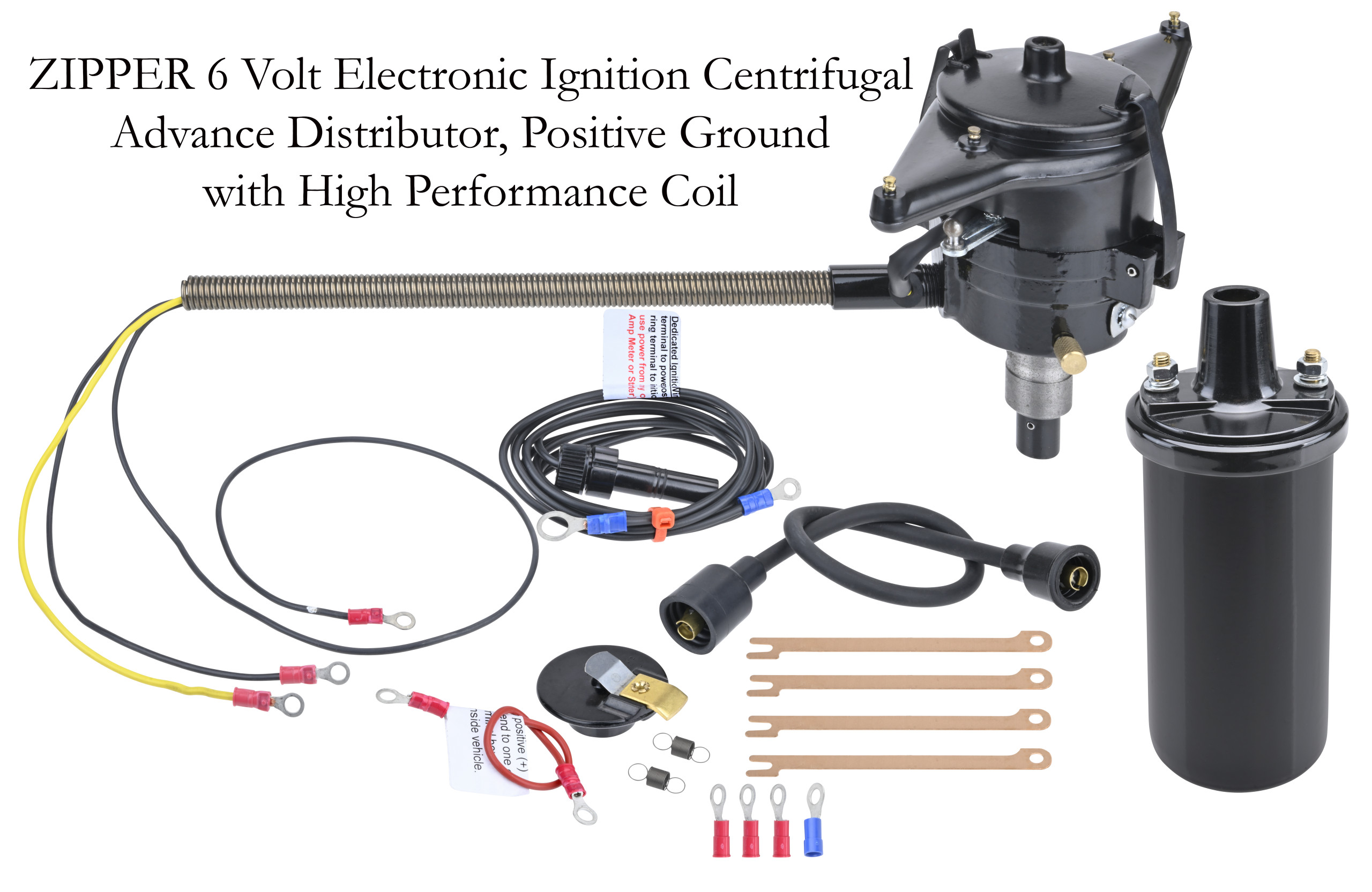
Ford Model A 6 volt positive ground electronic original look distributor with coil FSIZ6PK
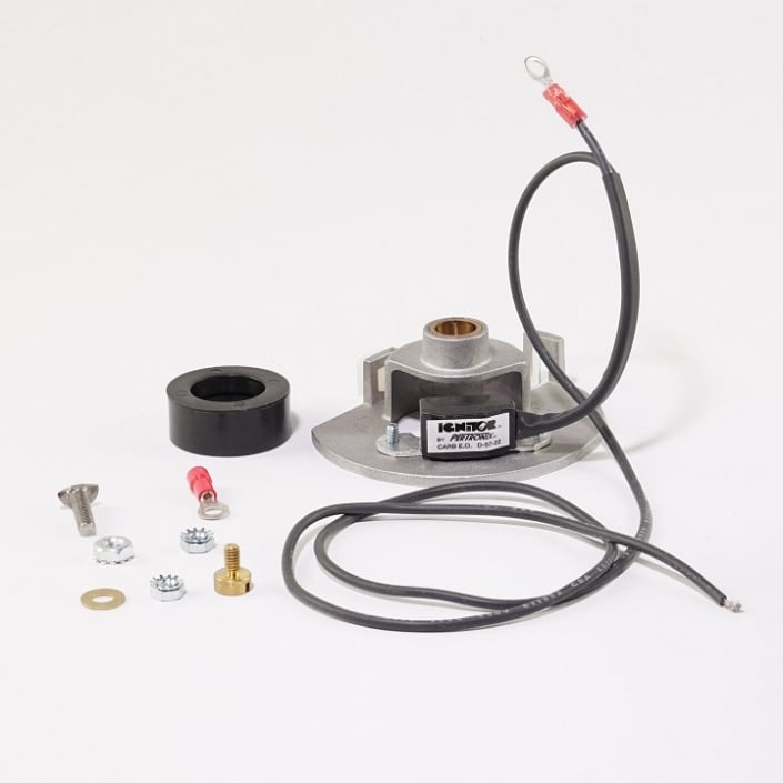
6Volt Positive Ground Ford Electronic Ignition Kit The Brillman Company
[DIAGRAM] 1955 Thunderbird 6 Volt Coil Wiring Diagram

FSI Electronic Ignition Centrifugal Advance Distributor, 6Volt Positive Ground, With or Without
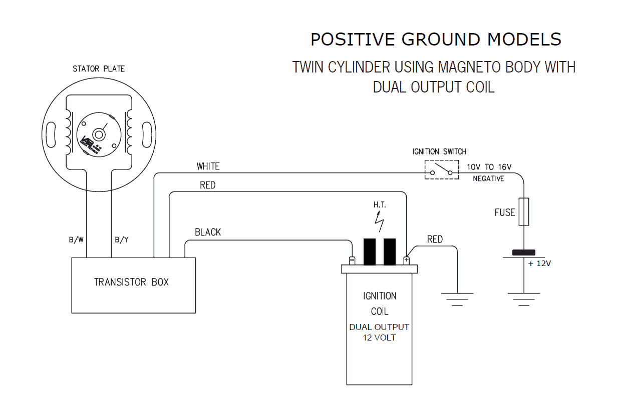
Tractor 6 Volt Positive Ground Wiring Diagram For Your Needs
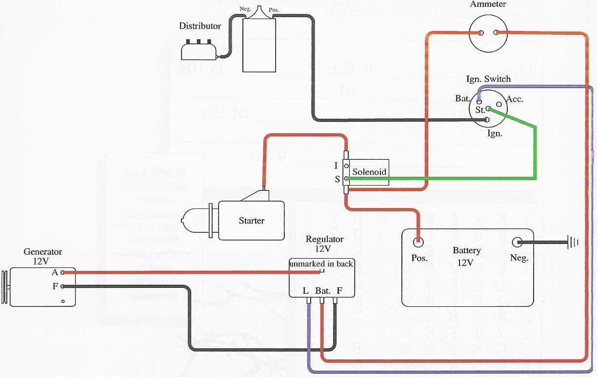
wiring diagram generator AllisChalmers Forum

Positive Ground Coil Automotive and Motorcycle Pinterest Ford explorer, Engine and Ford

Ford Model A 6 Volt positive ground electronic distributor with coil FSID6PK

✨ 6 Volt Positive Ground Wiring Diagram ⭐⭐⭐⭐⭐

C Farmall Wiring Diagram

How To Jumpstart A 6 Volt Positive Ground?
6 Volt Positive Ground Wiring Diagram Farmall A Tractor schematic and wiring diagram
![[22+] 1953 Ford Jubilee 6 Volt Wiring Diagram, Vintage 6 Volt Positive Ground Wiring Diagram [22+] 1953 Ford Jubilee 6 Volt Wiring Diagram, Vintage 6 Volt Positive Ground Wiring Diagram](https://lesmodela.files.wordpress.com/2017/10/wiring-diagramcolor2sm.jpg?w%5Cu003d760)
[22+] 1953 Ford Jubilee 6 Volt Wiring Diagram, Vintage 6 Volt Positive Ground Wiring Diagram
Technical Advice on my 6V positive ground schematic The H.A.M.B.
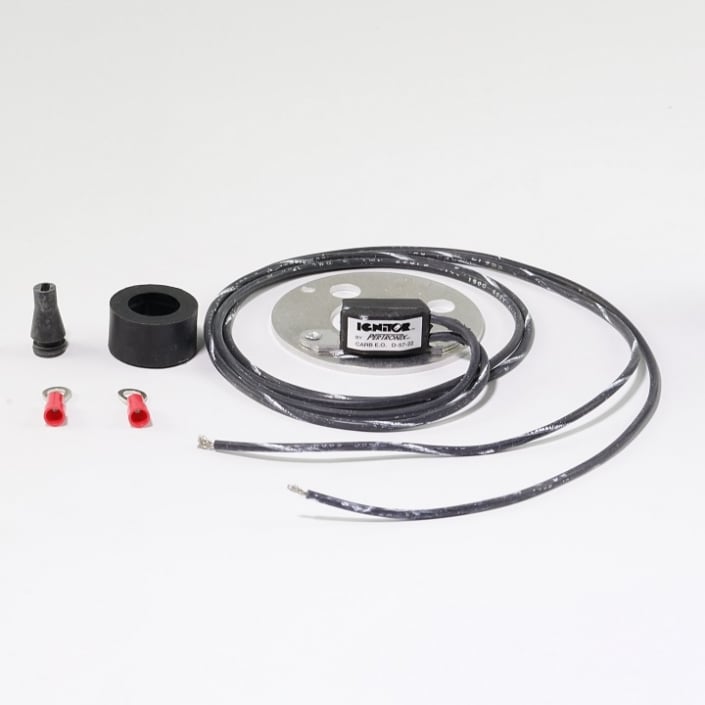
6Volt Positive Ground Electronic Ignition Conversion Kit The Brillman Company

1247XTP6 Ignition & Coil Conversion Kit; 6 Volt Positive Ground
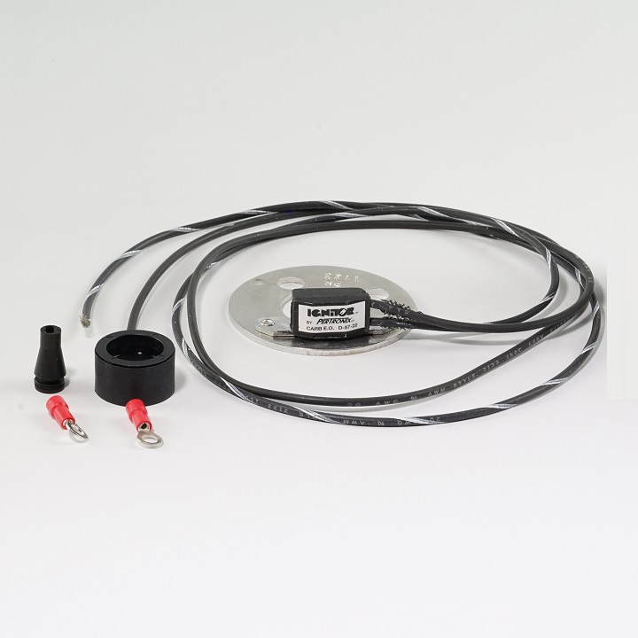
B3P6, 6 Volt Positive Ground Electronic Ignition Conversion Kit The Brillman Company
1. My solenoid only has a "S" terminal. Refer to pic. 2. I tested the battery on/off gauge and it actually shows either "charge" or "discharge" when 6V is applied to the terminals. By reversing the terminals it will change from either "charge" or "discharge". When no voltage is applied it reads "off".. jalopy43 said: Yes. it's known as 'polorizing the charging circut'. Generators put out DC current,with a positive side,and a negitive side. Alternators put out alternating current,switching positive,and negitive current,many times a second Diodes, act as a one-way valve,separating the poles. 'Sparky'.